Abstract: Circuit based on a buck/boost converter controller regulates current to a white LED, despite an allowed variaTIon of input voltage from 2.7V to 16.5V.
The advent of high-power LEDs capable of replacing incandescent bulbs has produced a need for circuits that efficiently match the LEDs to available power sources (batteries, car electrical systems, etc.). The circuits should also be able to regulate and control the LED light output, despite variaTIons in output voltage from the power source.
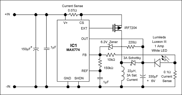
The circuit of Figure 1 starts and operates a 1A LED from a voltage that ranges from 2.7V minimum (the end of life for three alkaline primary cells) to 16.5V maximum (the maximum voltage for 12V automobile systems). OperaTIon over that range is stable and smooth, even with more than 1Ω of internal resistance at the power source.

Figure 1. Wide input-voltage range, high-power LED driver.
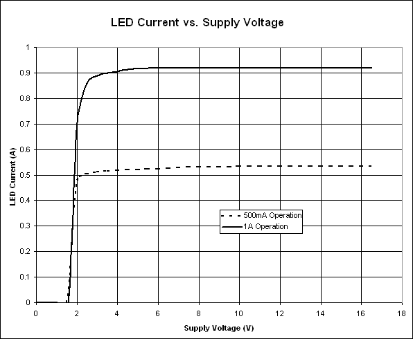
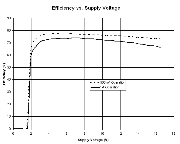
An inducTIve, buck-boost converter controller (IC1) with external MOSFET power switch is setup in a current-regulation loop using a 0.1Ω current-sense resistor in series with the power LED. (If the output circuit opens, the 6.2V Zener diode turns on, starting a voltage regulation loop.) Figure 2 shows the current regulation for 0.5A and 1A output currents, and Figure 3 shows the corresponding efficiencies, all plotted vs. the operating range of input voltage.

Figure 2. LED current vs. supply voltage for the Figure 1 circuit.

Figure 3. Efficiency vs. supply current for the Figure 1 circuit.
Replacing the 10kΩ feedback resistor (connected to the current-sense resistor) with a linear potentiometer of the same value enables efficient dimming of the LED. Starting from the maximum 1A regulation point set by the circuit values shown, the power-LED current (and hence its light output) can then be linearly swept through a range of more than 20:1.
A similar version of this article appeared as a Design Brief in the January 20, 2005 issue of ED magazine.


